2026-11-04
39
Faster wireless charging brings greater demands on thermal design. As Qi2 25W chargers, compact magnetic charging accessories, and multi-device charging stations become more common, manufacturers need effective ways to manage heat within increasingly limited space.
For product designers, the challenge extends beyond reducing a single component’s temperature. A successful thermal solution must support sustained charging performance, control enclosure temperatures, protect sensitive components, and fit the production process.
Thermal interface materials play an essential role by connecting heat-generating components to cooling structures. Silicone gap pads, dispensable thermal gels, phase change materials, and graphite heat spreaders offer different advantages depending on the charger’s construction.
This article explains how these solutions can be evaluated for practical wireless charging applications, with relevant options from Union Tenda.
Wireless charging generates heat through losses in the coils, magnetic materials, and power conversion circuitry. Compact enclosures and restricted airflow can make this heat difficult to dissipate.
If heat accumulates, the charger or receiving device may reduce charging power through its thermal controls. This makes sustained performance an important design target alongside the advertised charging power.
A thermal interface material helps replace insulating air gaps between a heat source and a cooling surface. However, its effectiveness depends on the complete heat dissipation path:
Heat source → thermal interface material → heat spreader or enclosure → surrounding air
Each stage matters. A high-performance TIM cannot compensate for an enclosure that has insufficient capacity to release heat.
Silicone thermal pads are suitable candidates when a charger has a controlled gap between a component and its cooling structure. Their preformed shape makes placement and inspection straightforward during assembly.
Potential applications include transferring heat from power components to an internal cooling plate or connecting a thermally designed PCB region to the charger base.
Union Tenda offers several grades for different thermal and mechanical requirements:
LC600 Thermal Silicone Pad: listed thermal conductivity of 6.0 ± 0.3 W/m·K.
LC800 Thermal Silicone Pad: listed thermal conductivity of 8.0 ± 0.5 W/m·K.
These products provide options for evaluating component-to-housing interfaces in compact charger assemblies.
Thermal conductivity is only one selection factor. Installed thickness, contact area, surface condition, and compression force also influence performance.
A pad that is too thin may leave incomplete contact. An excessively thick pad increases the heat transfer distance and may require more compression than the assembly can tolerate.
This is particularly relevant near fragile ferrite shielding or flexible PCB regions. Designers should confirm compression behavior under the actual assembly conditions instead of selecting a material solely by conductivity or hardness.
Explore Union Tenda’s Thermal Silicone Gap Pad range to compare available options.
Wireless charger circuit boards often contain components with different heights. When several components must connect to a shared cooling structure, managing multiple pad thicknesses can complicate assembly.
Dispensable thermal gels provide another approach. Material can be applied locally to accommodate irregular surfaces and dimensional variation.
Union Tenda’s LCF600 Two-Component Thermal Conductive Gel cures into a flexible, thermally conductive elastomer and supports automated dispensing.
This format is worth evaluating for:
Assemblies with varying component-to-housing gaps.
Multiple heat sources connected to a common cooling plate.
Production lines using controlled material dispensing.
Gel selection should account for dispensing equipment, mixing requirements, working time, curing conditions, and inspection methods.
Application volume also matters. Insufficient material can leave voids, while excessive material may spread into areas where it is unwanted.
For serviceable products, establish rework requirements early. Removing and replacing a cured interface may require a different process from replacing a preformed pad.
View Union Tenda’s Thermal Gel products for additional material options.
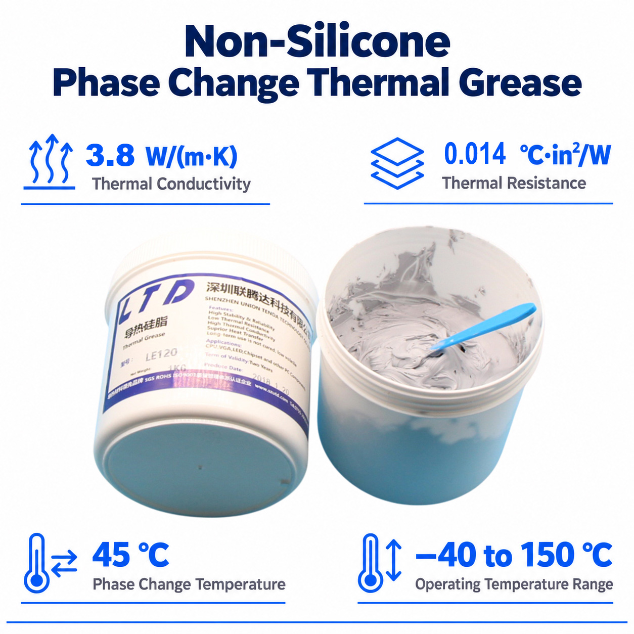
Phase change thermal interface materials soften at a specified transition temperature, allowing them to conform more closely to mating surfaces.
They are candidates for thin interfaces where surface flatness, spacing, and mounting pressure are carefully controlled. In a wireless charger, this may include a suitable power component connected to a closely fitted cooling surface.
Union Tenda’s Thermal Phase Change Materials provide options to investigate for these applications.
Before selection, confirm:
Whether the operating temperature reaches the material’s intended transition range.
Whether the mounting arrangement maintains reliable contact.
Whether the selected grade meets electrical insulation requirements.
Whether the interface remains stable through repeated heating and cooling.
Phase change materials should be evaluated according to the interface geometry. They generally serve a different role from pads or gels used to bridge larger assembly gaps.
Slim magnetic charging pucks often have limited space for conventional cooling structures. In these designs, spreading heat away from a localized hot spot can be useful.
Graphite sheets conduct heat strongly along their plane, helping distribute heat across a larger internal area.
Union Tenda’s LGS1500 Synthetic Graphite Sheet offers a thin heat-spreading option. Its published properties distinguish between in-plane and through-plane thermal conductivity, which should be considered when designing the heat flow path.
Graphite is electrically conductive. Its placement therefore requires suitable electrical isolation and evaluation within the wireless charging assembly.
Conductive heat spreaders near the coil can affect electromagnetic behavior, losses, and foreign object detection. Designers should assess the coil, ferrite shielding, thermal interface, and heat spreader as a complete arrangement.
Graphite may complement a pad or gel by spreading heat after it crosses an interface. The benefit depends on placement and the availability of a suitable path for heat to leave the enclosure.
The following table provides starting points for engineering evaluation.
|
Application requirement |
Material option |
Union Tenda reference |
Main selection considerations |
|
Defined gap between components and a cooling structure |
Silicone thermal pad |
Thickness, contact pressure, electrical insulation |
|
|
Uneven component heights or automated application |
Dispensable thermal gel |
Dispensing volume, curing, coverage, rework |
|
|
Thin interface with closely fitted surfaces |
Phase change TIM |
Transition temperature, surface flatness, retention |
|
|
Localized hot spots within a slim enclosure |
Graphite heat spreader |
Heat-flow direction, electrical isolation, coil interaction |
Prioritize a short thermal path while maintaining reliable contact across manufacturing tolerances. Pad compression and heat-spreader placement should preserve coil position and protect magnetic shielding.
Evaluate the station with all supported charging positions operating simultaneously. Shared cooling structures may accumulate heat that is not apparent during single-device testing.
Cabin temperature, solar loading, vibration, and restricted airflow create additional design constraints. Material qualification should address these conditions, together with the module’s cooling structure and any active cooling provisions.
Material datasheets help narrow the options, but final selection requires testing in the assembled product.
A useful validation program should measure component temperatures, enclosure temperatures, sustained charging power, and the onset of thermal power reduction. Tests should cover supported devices, representative phone cases, ambient conditions, and placement variations.
After thermal stack changes, verify electromagnetic performance and foreign object detection as well. Thermal improvements must remain compatible with the charger’s power transfer and protection functions.
For meaningful comparisons, keep ambient temperature, receiving-device battery state, charging load, and test duration consistent.
Effective wireless charger cooling starts with understanding the assembly: where heat is generated, how large the interface gaps are, how much pressure components can tolerate, and where the heat will ultimately go.
Union Tenda’s portfolio includes silicone thermal pads, thermal gels, phase change materials, and graphite sheets for evaluating different parts of that thermal path.
Explore our Wireless Charging and Thermal Solution, or contact Union Tenda to discuss your application.
Share your charger layout, interface dimensions, operating conditions, temperature targets, and assembly requirements to help identify suitable material candidates for testing.